Designed a manual
compacting waste disposal system which has optimized space and segregation
capability of a household recycling bin with aesthetic compatibility. Utilized
analytical product development tools like touchpoint model, QFD, down selection
matrix to arrive at product design, Kansei methodology to convert the
qualitative aesthetic input through consumer surveys into quantitative
attribute selection, LIDS methodology for material and manufacturing process
selection and cost model with break-even analysis assuming .The proof of
concept was validated using conjoint analysis.
Abstract:
The current waste disposal process in United States households is inefficient in terms of indoor space taken up by trash and recyclables, and time spent emptying the indoor bins. Survey of homeowners indicates frustration with these two steps of the recycling process as well as lack of knowledge on waste separation. The goal of this project is to design a home waste disposal system that can optimize indoor space and decrease the number of times needed to empty the indoor bins. The All-in-one Home Waste Disposal System is a three compartment bin for recyclables (plastic and paper), trash and returnable items. The three compartments are well labelled in order to inform the user on how to properly segregate waste. The bin has compacting capabilities in the trash and recycling sections. This is achieved by using a manual compacter with an increased mechanical leverage system. The user provides the compression force using a handle bar lever that attaches to the sides of the bin. This lever slides down in front of the bin and has two plungers attached to it, which compresses the recycle and trash compartments of the bin. The design was developed and tested using Solid Works and FEM to check stresses in the handle bar and plungers. A clean professional aesthetic look was applied to the All-in-one Home Waste Disposal System in order to blend it with modern household appliances. User tests will be used to evaluate the effectiveness of our product in comparison to the current household bin system. This product is expected to be competitive with normal indoor trash bins with increased volume optimization and segregation capability.

Highlights:
Market Research and downselection:
 |
| Combination Table of different ideas |
 |
| Downselection Matrix |
Ergonomic study and product design:
 |
| OSHA Max standards for pushing and pulling |
 |
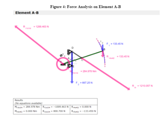
| Autodesk Forceeffect for force analysis in linkages |
 |
| Trash compacting mechanism (Left) and Recyclables compacting mechanism(right) |
 |
| SolidWorks stress and displacement analysis for critical components |
 |
| Features of All in One Compacter |
Material selection and Mass Manufacturing:
 |
| LIDS circle for electric compacter mass manufacturing |
 |
| MET Matrix for material selection |
 |
| Cycle Time Calculation for mass manufacturing |
 |
| Capital Equipment layout for mass manufacturing |
Financial Forecast:
 |
| Profit Model |
Proof of Concept at Design Expo 2016 at University of Michigan
Validation of design using conjoint analysis
 |
Attribute comparison chart using customer feedback
|