Monday 30 December 2013

SSS

SSS(Save,Sustain and Succeed)

Introduction:


Idea!

 When we make the wheels of the train to act as a turbine the kinetic energy of the wheels could be eventually be converted to electric energy. This electric energy can be stored in secondary cell batteries or be directly used in powering up fans, lights and cooling systems in the train.If this idea is extended, this power generated can also be used in powering up the engine, which will eventually make all trains electric and even the fans in our homes can be made as a self UPS system. This is applicable to automobiles including cars, autos and lorries designed as per Indian norms. 

Theory:

The mad idea obeys the law of conservation of angular momentum and also the law of conservation of energy. According to the idea, every rotating machine can be made as an energy producer. As every rotatory object has kinetic energy acting on it, this energy can be suitably converted into reusable form of energy by making its rotatory parts act as a turbine which converts into electricity(Like a DC generator). When seeing it in a small scale, every rotatory household appliance like fans can act as a Self Installed UPS (SIUPS).

Why This?


For example, the Railways in India are a large network covering 64,215 km of track and 7083 stations across the country. It’s the fourth largest railway in the world. It carries 30 million passengers daily and the electricity that is needed to providethem comfort and luxury is about 2.5% of the country’s total electricity consumption. When we make the wheels of the train to act as a turbine the kinetic energy of the wheelscould be eventually be converted to electric energy. This electric energy can be stored in secondary cell batteries or be directly used in powering up fans, lights and cooling systems in the train. This idea can be extended to household appliances like fans to act as SIUPS. Consumption of electricity by Traction and Railways in last five decades (Giga Watt hour) - 1970 – 71 1,364 1975 – 76 1,855 1980 – 81 2,266 1985 – 86 3,182 1990 – 91 4,112 1995 – 96 6,2232000 – 01 8,213 2005 – 06 9,944 2006 – 07 10,800 2007 – 08 11,108 2008 – 09 11,425 2009 – 10 12,408 2010 – 11 14,003 According to an estimate, the railway sector’s demand for electricity will grow by seven percent annually and by 2020 it will have a projected energy demand of 37,500 kWh (million kilowatt hour)!!!..which is astonishing.

Implementation:

1)First this idea can be tested on trains which travel a distance of 500km and test the amount of electricity consumption that is reduced.
 2)The generated energy through the wheels of the train will be used to power the lights and fans in the train.
 3)Then after the success stories of the tested trains,the mad idea can be implemented in 100 long distance trains and it will considerably reduce the electricity consumption. 
4)The whole of IRCTC network can be made to generate sustainable amount of electricity to power lights and fans in the trains

EFFECTS:


 1)If implemented the electric power
consumption by the IRCTC can be considerably reduced from 15000 GWh to 5000 GWh.
 2) Indian Railways pays over Rs 5,000 crores every year on account of traction energy charges which constitutes about 20 percent of total revenue budget of Railways.If the mad idea is executed IRCTC will only be paying around 40 %(approx.) 3)When the traditional fans in our houses are made to act as SIUPS as told before, when power cut or failure takes place, these fans can rotate using the energy stored while it was running. 
4) Helps in conserving and sustaining energy in an efficient manner.
 5)Reduces power consumption in houses which is the need of the hour!

Sunday 29 December 2013

Flapping Wing Mechanism or Ornithopter!

Ornithopter

(At "IGNITION" Mechanical Symposium at SVCE Sriperamdur,Chennai)

An Ornithopter model

Introduction:

     This is a futuristic kinematic mechanism made by Balachandar,Ashwin and myself (SVCE,Mech II yr) with the assistance of college faculty.This is called as "Ornithopter" or "The Flapping Wing Mechanism".The basic idea is to find the advantages of an aircraft having flapping wings.The idea starts from the days of Ramayana where it says Raavana used a "Pushpakavimaana" to fly.(flapping wings).We first made an Autocad 3D design and then went for the model in wood and machined it with lathe(serious work!).
The Model
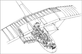
Model made with the ref. of this 2D drawing


The bird wing, the ideal!

Naturally, the great archetype for technical flapping wings is the living bird wing. His great effectiveness due to his manifold possibilities to move purposeful and to change the shape will certainly be unobtainable in aero modelling for a long time. This is also true for his weight distribution and his sensor technology.
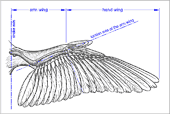
In this drawing by K. Herzog the anatomic subdivision of the bird's wing in arm- and hand section is pictured. It can also to be used advantageously when describing technical flapping wings. The longitudinal parts of these wing sections are rather different depending on bird species.

Shearflex principle

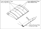
flapping wing with the Shearflex Principleornithopter wing design by J. M. HarrisDrawing of the model by Dennis Williams
Here an aeroelastic twistable profiled flapping wing according to the Shearflex Principle. This system makes a relatively inelastic covering applicable. If the twisting along the wing is constant and not to excessive, the airfoil contour accuracy is therefore very good.
Here, the twist elasticity will mainly be determinate by the spar designed as wing leading edge.
This system was invented by Professor literature James D. DeLaurier and Jeremy M. Harris (Canada 1994).
The ornithopter with its tripartition of the flapping wing is interesting, too. Jeremy M. Harris 1977 has applied it for patent.


Application range


Profiled flapping wings or double-sided covered wings may work with a very high efficiency. With their mostly relatively low flapping frequency and the small operating range of lift coefficient of a simple airfoil not much thrust can be produced. Not, at least, if the full lift must be generated concurrently (flying with lift). Therefore, profiled flapping wings are suited especially for a level flight, the gently inclined climbing flight and of course for changing to gliding flight.

External links to other flapping wing designs

  1. Alphonse Pénaud, (1850 - 1880):
    http://www.ctie.monash.edu.au/hargrave/penaud.html
  2. Video about a flapping wing model by Cenek Chalupsky:
    http://ovirc.free.fr/Clips_video.php
  3. Construction method of the flying wing model by Jean-Louis Solignac:
    http://ovirc1.free.fr/solignac-ornitho.htm
  4. Thrust-Wing model ENTOID by Velko T. Velkov:
    http://velkovelkov.blogspot.com/2009/09/entoid.html
  5. The Double flapping wing airplane by Karl-Heinz Helling is flying:
    http://www.modellbau-thiele.de/schlagfluegel.htm
    http://www.mfc-rossendorf.de/fileadmin/Projekte/SchlagfluegelProjekt/SchlagfluegelProjekt.htm
  6. Report about Percival H. Spencer:
    http://www.seabee.info/spencer.htm
  7. The Schwan 1 by Walther Filter in the Aviation Museum Hannover-Laatzen,
    point of view at Scale Soaring UK and Air-Britain:
    http://www.scalesoaring.co.uk/VINTAGE/Documentation/Schwan/Schwan.html
    http://www.abpic.co.uk/results.php?q=Filter+Schwan&fields=all&sort=latest&limit=10
  8. Fanning-out wings of the Birdman Georges Fraisé:
    http://ovirc.free.fr/GFraise.php
  9. Fanning-out wing tips at the Ornithopter Project by Ryszard Szczepañski:
    http://www.ornithopter.com.pl
  10. Close-up view of an orange colored Dragonfly:
    http://www.grahamowengallery.com/photography/dragonfly_photography.html


We enjoyed doing this project for our Mechanical Symposium and learnt the difficulties of designing and manufacturing a working model!